


40460
No.90, sec. 2, Hwa Mei Str.,
Taichung, Taiwan.
Latest News
HOME / News
21.May.2025
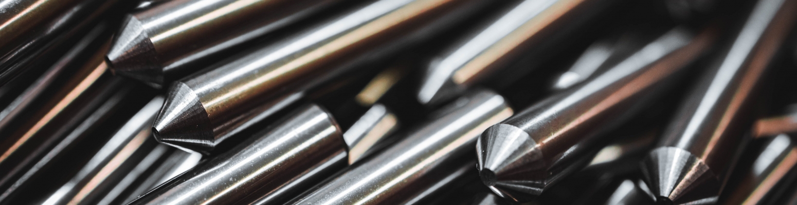
How to Use Carbide Thread Mills
How to Use Carbide Thread Mills
Carbide thread mills are essential tools in precision machining, offering high wear resistance and accuracy for threading applications in engineering plastics and metals. Unlike traditional tapping, thread milling allows for controlled, layer-by-layer material removal, reducing machining pressure and enhancing thread quality. This guide provides comprehensive insights into using carbide thread mills effectively, from preparation to execution.
What Is a Carbide Thread Mill?
A carbide thread mill is a cutting tool used to create threads through helical interpolation. Unlike taps that cut the entire thread profile in one pass, thread mills gradually remove material, making them suitable for hard-to-machine materials and applications requiring high precision.
Types of Thread Mills
| Type | Features | Machining Characteristics |
|---|---|---|
| Single-Profile | Single thread form on the cutter | Requires multiple passes; stable but slower |
| Triple-Profile | Three thread forms on the cutter | Faster than single-profile; still needs multiple passes |
| Full-Profile | Full thread form along the cutter | Completes thread in one pass; highest efficiency |
Efficiency Comparison: Why Choose Full-Profile Thread Mills?
Consider threading an M14×2.0 thread to a depth of 14mm:
| Thread Mill Type | Number of Passes | Estimated Time (5 seconds per pass) |
|---|---|---|
| Single-Profile | 7 | 35 seconds |
| Triple-Profile | ~2.5 | 12–15 seconds |
| Full-Profile | 1 | 5 seconds |
Efficiency Gains:
- Up to 6× faster than single-profile thread mills
- Up to 3× faster than triple-profile thread mills
Using full-profile thread mills not only reduces machining time but also minimizes tool wear and enhances thread consistency.
Preparation Before Thread Milling
- Verify Hole Diameter:
- Ensure the pre-drilled hole matches the required minor diameter for the thread.
- For M14×2.0 threads, a Ø12mm hole is recommended.
- Proper Tool Holding:
- Use ER collets or heat-shrink holders for secure clamping.
- Minimize tool overhang to reduce deflection and vibration.
- Secure Workpiece:
- Ensure the workpiece is firmly clamped to prevent movement during machining.
Recommended Machining Parameters
For engineering plastics like POM, PC, or PEEK:
| Parameter | Recommended Range |
|---|---|
| Spindle Speed (RPM) | 1680–2500 |
| Feed per Tooth (fz) | 0.05–0.07 mm/tooth |
| XY Feed Rate | 336–700 mm/min |
| Z-Axis Feed (per pass) | 2.0 mm (matching thread pitch) |
| Machining Approach | Complete in three passes without interruption |
Thread Milling Process Steps
- Helical Interpolation:
- Use G02 or G03 commands for circular interpolation.
- Set Parameters:
- Define I (radius offset) and K (Z-axis increment per revolution) values.
- Continuous Machining:
- Execute the threading operation without pauses to ensure thread integrity.
Common Issues and Solutions
| Issue | Possible Cause | Solution |
|---|---|---|
| Tool Vibration | Excessive tool overhang or low spindle speed | Reduce overhang; increase spindle speed |
| Threads Not Formed | Missing Z-axis movement in program | Include synchronized Z-axis movement |
| Blunt Thread Peaks | Slow feed rate or material melting | Increase feed rate; use air cooling |
| Misaligned Threads After Rework | Workpiece repositioned or interrupted process | Avoid interrupting the threading process |
Key Considerations
Continuous Operation: Complete the threading process in one go to prevent misalignment.
Cooling Methods: Use air cooling or Minimum Quantity Lubrication (MQL) for plastics to avoid melting.
Stable Setup: Ensure the machine and workpiece setup is rigid to minimize vibrations.
Conclusion
Proper use of carbide thread mills enhances threading efficiency and quality. Opting for full-profile thread mills can significantly reduce machining time and improve thread consistency, making them ideal for high-precision applications.